Project Details
Summary
Formula SAE is a competition in which students design, manufacture, and race a 1/3rd scale Formula 1 car within a year. Unlike Formula 1 cars, however, our car needs to be able to accommodate drivers of all sizes in an ergonomic manner. There are two main ways to do this:
- Adjust the position of the driver seat
- Adjust the position of the pedals
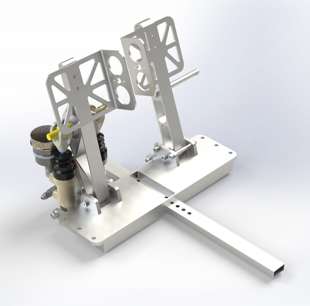
Since it is generally more difficult to move the driver, we decided to create an adjustable pedal assembly. To begin the design process, I defined a set of requirements:
- Withstand the 2000 N emergency braking force as specified by the rules
- Allow for the mounting of a brake over-travel sensor as specified by the rules
- Allow for a vertical Master Cylinder configuration to accommodate a shorter chassis
- Maintain a high level of stiffness to ensure driver confidence
- Maintain a mass of 2.5 lbm or under
- Ensure quick adjustability
With these requirements in hand, I started my design.
Brainstorming and Hand-Calcs
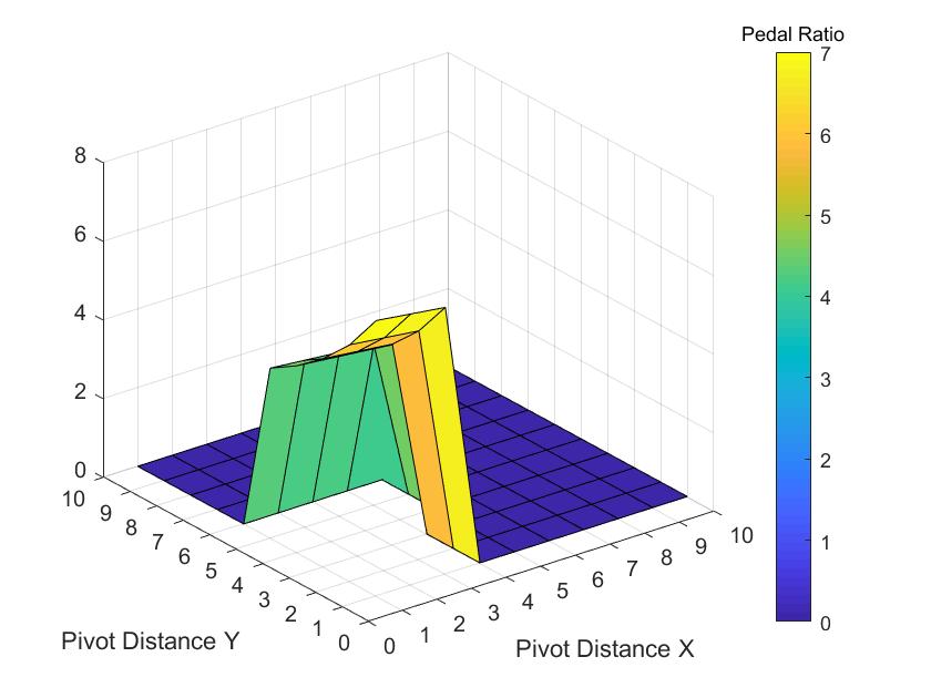
Before running NX, another team member and I researched adjustable pedal boxes, and asked team drivers for their preferences. I then wrote a MatLab script to optimize the pivot point location in order to gain the maximum mechanical advantage for the driver. The script solves for the pedal ratio of all possible geometry configurations and returns the maximum value. The code can be seen below.
MatLab Code
clear;clc;close all; %clear workspace

%//////////////////////////////////////////////////////////////////////////
%initial variable declaration

Pedal_length = 9.25; %Define brake pedal length
Pedal_Start_Angle = 90; %Define pedal start angle based on driver pref
Pedal_Travel = 2; %Define desired travel based on driver preference
Master_StartMin = 5.75; %Define master cylinder max start dimension
Master_StartMax = 6.875; %Define master cylinder min start dimension
Master_EndMin = 5.5; %Define master cylinder max end dimension
Master_EndMax = 6.5; %Define master cylinder min end dimension
Max_Travel = 0.5; %Define Master cylinder desired travel

CXX = linspace(1.5,4,10); %define search matrix gran w/ respect to x
CYY = linspace(-1,0.5,10); %define search matrix gran w/ respect t to y
D = linspace(5,8,25); %H distance search matrix
%CXX = 1.5; %Fix X if neccesary
%CYY = -1; %Fix Y if neccesary
%D= 5.75; %Fix D if neccesary

%//////////////////////////////////////////////////////////////////////////
%main function run

A = run_matrix(Pedal_length,CXX,CYY,D,Pedal_Start_Angle,Pedal_Travel...
    ,Master_StartMin,Master_StartMax,...
    Master_EndMin,Master_EndMax,Max_Travel); %Run search script
Max_Pedal_Ratio = max(A,[],'all'); %search for max value
[x,y,z] = find(A == Max_Pedal_Ratio);%display maximum value based on indiex
B = A(:,:,z); %Truncate array based on max A
hold off; %ensure plot over is off.
surf(B,'MarkerFaceColor','g'); %plot results
xlabel ('Pivot Distance X'); %set x label
ylabel ('Pivot Distance Y'); %set y label
hcb = colorbar; %enable colorbar for visibility
set(gca,'XLim',[0 10]); %Xbox Limit
set(gca,'YLim',[0 10]); %Ybox Limit
set(gca,'XTick',[0 1 2 3 4 5 6 7 8 9 10]); %X tick spacing
set(gca,'YTick',[0 1 2 3 4 5 6 7 8 9 10]); %Y tick spacing
title(hcb,'Pedal Ratio') %Chart title

%//////////////////////////////////////////////////////////////////////////
%Function for matrix level multiplication

function [result] = run_matrix(P,CXX,CYY,D,S_Angle,P_Travel,...
    Master_StartMin,Master_StartMax,Master_EndMin,Master_EndMax,Max_Travel)

    Cx_length = size(CXX,2); %Store array size
    Cy_length = size(CYY,2); %Store array size
    D_length = size(D,2); %Story array size
    for i = 1:Cx_length %CX layer cycle
        current_Cx = CXX(1,i);
        for j = 1:Cy_length %CY layer cycle
            current_Cy = CYY(1,j);
            for k = 1:D_length %D layer cycle
            current_D = D(1,k);
            A(i,j,k) = crunch(P,current_Cx,current_Cy,current_D,S_Angle,...
                P_Travel,Master_StartMin,Master_StartMax,Master_EndMin,...
                Master_EndMax,Max_Travel);  %Send to geometry solver
            end
        end
    end
    result = A; %Return result
end

%//////////////////////////////////////////////////////////////////////////
%Function for pedal box specific calculations

function [ratio] = crunch(P,CXX,CYY,D,S_Angle,P_Travel,Master_StartMin,...
    Master_StartMax,Master_EndMin,Master_EndMax,Max_Travel)
    phi = atand(CYY/CXX); %calculate sub angle of pedal
    theta1 = S_Angle - phi; %gives anti-travel
    travel = 360*P_Travel/(P*2*pi); %Calculates possible travel
    theta2 = S_Angle-phi-travel; %Calculates depressed angle
    CA = (CXX*CXX + CYY*CYY)^0.5; %pythagorean theorem for length

    MC_Initial = ((CA^2) + (D^2) - (2*CA*D*cosd(theta1)))^0.5;
    %initial master cylinder length calculation
    MC_Final = ((CA^2) + (D^2) - (2*CA*D*cosd(theta2)))^0.5;
    %final master cylinder length calculation
    travel = MC_Initial - MC_Final;
    %Travel distance check

    %Check if master cylinder can physically achieve travel otherwise 0
    if  ((MC_Initial < Master_StartMin ) ||(Master_StartMax < MC_Initial))
        ratio = 0;
    elseif  ((MC_Final < Master_EndMin ) ||(Master_EndMax < MC_Final))
        ratio = 0;
    elseif travel > Max_Travel
        ratio = 0;
    else
        ratio = P_Travel/travel;
    end
end